
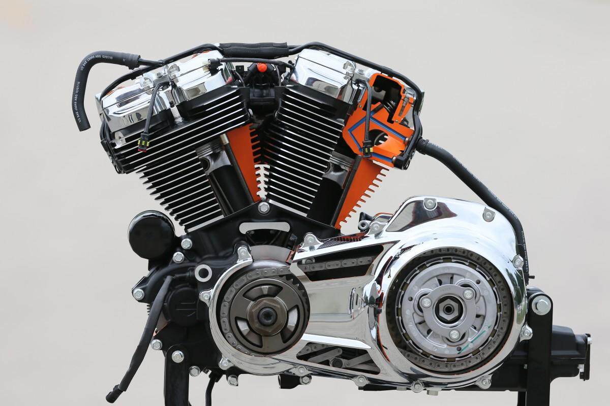
I. The Intriguing Structure of Motorcycle Engine System
(I) Cylinder and Piston Assembly
- Cylinder Block
- The motorcycle cylinder block is a crucial component of the powerplant. It provides the chamber for the combustion of the air-fuel mixture. Commonly found in cast iron or aluminum alloy varieties. Cast iron cylinders offer excellent wear resistance and strength, capable of withstanding high pressures but are relatively heavier. Aluminum alloy cylinders boast the advantage of being lightweight and have superior heat dissipation properties. The bore diameter of the cylinder varies depending on the motorcycle’s displacement. For small-displacement motorcycles, it typically ranges from 50mm to 70mm, while large-displacement ones can exceed 100mm. The inner surface of the cylinder is usually honed to achieve a surface roughness of Ra0.4 – Ra0.8 microns, ensuring smooth piston movement and optimal sealing.
- Piston
- The piston undergoes reciprocating motion within the cylinder, converting the energy from combustion into mechanical power. Typically made of aluminum alloy, with the piston crown coming in various shapes such as flat, domed, or concave depending on the engine’s design requirements. The piston skirt serves as a guide and bears the side forces. To adapt to different operating conditions, the skirt may have designs like oval or barrel shapes. The piston is equipped with rings, usually two compression rings and one oil control ring. The compression rings seal the cylinder to prevent air-fuel mixture leakage. The oil control ring scrapes off excess oil from the cylinder wall, maintaining lubrication and reducing oil consumption. The ring gap of the piston rings is typically in the range of 0.2mm – 0.4mm for the opening gap and 0.03mm – 0.07mm for the side gap.
(II) Crankshaft and Connecting Rod Mechanism
- Crankshaft
- The crankshaft is the powerhouse of the engine, transforming the piston’s reciprocating linear motion into rotational motion. Forged from high-quality alloy steel and subjected to precision machining and heat treatment. The main journal diameter varies according to the engine’s displacement and power output. Generally, it falls between 20mm and 40mm. The crank throws are designed for balance and strength, and undergo dynamic balancing tests to ensure stability at high speeds. In a motorcycle engine, the crankshaft speed ranges from 800 – 1500rpm at idle and can reach up to 8000 – 12000rpm or even higher during high-speed operation.
- Connecting Rod
- The connecting rod links the piston to the crankshaft, transmitting forces during operation. Made of high-strength aluminum alloy or alloy steel. The big end of the connecting rod is connected to the crankshaft using a split structure and fastened by bolts. The small end is connected to the piston pin and contains a bushing to minimize wear. The length and thickness of the connecting rod are optimized according to the engine design. The connecting rod ratio (the ratio of the connecting rod length to the crank radius) is generally between 3 and 5, which influences the engine’s performance characteristics.
(III) Valve Train Components
- Valves
- The valves play a vital role in controlling the intake of fresh air-fuel mixture and the exhaust of burned gases. There are intake valves and exhaust valves, usually made of high-temperature-resistant alloy steel. The intake valve diameter is often slightly larger than the exhaust valve to enhance intake airflow. The valve head diameter ranges from 20mm to 35mm, and the valve stem diameter is between 5mm and 8mm. The valve guide provides guidance for the valve’s movement. The valve spring ensures proper sealing when the valve is closed. The preload of the valve spring is typically between 30N and 50N.
- Camshaft
- The camshaft controls the opening and closing times and lifts of the valves through its cam lobes. Made of high-quality steel and heat-treated for increased surface hardness and wear resistance. The cam lift is designed based on the engine’s performance requirements and generally ranges from 6mm to 12mm. In a four-stroke engine, the camshaft speed is in a 1:2 ratio with the crankshaft speed. Connected to the crankshaft via a timing chain or belt to ensure accurate valve timing.
(IV) Fuel Supply System
- Carburetor (in some non-EFI models)
- The carburetor mixes fuel and air to create a combustible mixture. Comprised of a float chamber, main jet, idle jet, and more. The float chamber regulates the fuel level via a float to maintain a stable fuel supply pressure. The main jet diameter is typically between 0.8mm and 1.2mm, supplying different amounts of fuel depending on the engine’s operating conditions. The idle jet provides a small amount of fuel during idle to ensure stable engine operation. The air filter of the carburetor should be cleaned or replaced every 2000 – 3000 kilometers if operating in a dusty environment to ensure clean air entering the carburetor.
- Electronic Fuel Injection (EFI) System (common in modern motorcycles)
- The EFI system consists of fuel injectors, fuel pumps, and various sensors. The fuel injector precisely sprays fuel according to the commands from the engine control unit (ECU). The injection pressure usually ranges from 250kPa to 350kPa. The fuel pump transfers fuel from the tank to the injectors. The flow rate depends on the engine’s demand and can be between 30L/h and 80L/h. Sensors like the air flow sensor, throttle position sensor, and crankshaft position sensor provide essential engine operating data to the ECU for accurate fuel injection and ignition timing control.

II. Working Principles of Motorcycle Engine System
(I) Four-Stroke Cycle Principle
- Intake Stroke
- The piston descends from top dead center (TDC) to bottom dead center (BDC). At this time, the intake valve opens while the exhaust valve remains closed. The air-fuel mixture is drawn into the cylinder due to the negative pressure created inside. The duration of this process varies with engine speed and is typically between 180° and 220° of crankshaft rotation.
- Compression Stroke
- The piston moves from BDC to TDC. Both valves are closed, and the air-fuel mixture is compressed. The compression ratio, a key parameter for engine performance, generally ranges from 9:1 to 13:1 for motorcycle engines. As the mixture is compressed, its temperature and pressure increase, preparing it for combustion.
- Power Stroke
- As the piston nears TDC, the spark plug ignites the compressed air-fuel mixture. The rapid combustion and expansion generate immense pressure, pushing the piston down and driving the crankshaft to rotate, producing power. The peak gas pressure can reach 3MPa – 6MPa, and the temperature can soar to 2000℃ – 2500℃.
- Exhaust Stroke
- The piston ascends from BDC to TDC. The exhaust valve opens while the intake valve remains closed, expelling the burned gases from the cylinder. The exhaust process lasts for about 180° – 220° of crankshaft rotation to ensure complete removal of the waste gases.
(II) Two-Stroke Cycle Principle (brief overview)
The two-stroke engine’s working cycle includes intake, compression, power generation, and exhaust, all completed in two strokes. During the downward stroke of the piston, intake and compression occur. On the upward stroke, combustion and exhaust take place. Although it has a simpler structure, it often has poorer fuel economy and emission performance compared to four-stroke engines.
III. Maintenance Secrets of Motorcycle Engine System
(I) Regular Engine Oil Changes
- Replacement Interval
- For mineral oil, change it every 1000 – 2000 kilometers. Semi-synthetic oil is replaced every 2000 – 3000 kilometers, and fully synthetic oil every 3000 – 5000 kilometers. The engine oil capacity varies depending on the motorcycle model, usually ranging from 0.8L to 2L. Before changing the oil, warm up the engine for 5 – 10 minutes to ensure proper oil circulation. Then, drain the old oil by loosening the oil drain bolt.
- Oil Selection
- Choose the appropriate engine oil based on the motorcycle’s usage environment and engine type. For high-temperature driving or aggressive riding, select oil with a higher viscosity rating such as SAE 40 or SAE 50. In cold climates during winter, opt for oil with good low-temperature flow properties like SAE 5W – 30 or SAE 0W – 40. Pay attention to the oil’s quality grade as per the API standard, which includes grades like SJ, SL, SM, and SN. Higher grades offer better performance.
(II) Clean Air Filter Maintenance
- Cleaning Frequency
- In dusty environments, clean the paper air filter every 1000 – 1500 kilometers, and the sponge air filter every 500 – 1000 kilometers. Use compressed air at a pressure of 0.2MPa – 0.3MPa to blow from the inside out to remove dust and debris.
- Replacement Interval
- The paper air filter should be replaced every 5000 – 8000 kilometers. If the sponge air filter shows signs of aging, damage, or reduced filtering efficiency after cleaning, replace it promptly.
(III) Cooling System Checks
- Coolant Inspection
- Inspect the coolant level every 2000 – 3000 kilometers. The level should be maintained between the upper and lower marks of the coolant reservoir. If low, add the same type of coolant. Coolants are typically ethylene glycol or propylene glycol based. Do not mix different types of coolant. Regularly check the coolant’s freezing point, ideally once every two years, to ensure it won’t freeze in the local climate.
- Cooling System Cleaning
- Clean the cooling system every 10000 – 15000 kilometers. Use a specialized cooling system cleaner as per the instructions. Run the engine for 10 – 15 minutes with the cleaner added, then drain the cleaner and old coolant. Rinse the system with clean water and refill with fresh coolant.
(IV) Valve Clearance Adjustment
- Adjustment Interval
- Check and adjust the valve clearance every 5000 – 8000 kilometers. Different motorcycle engines have varying valve clearance standards. Generally, the intake valve clearance is between 0.08mm and 0.12mm, and the exhaust valve clearance is between 0.10mm and 0.15mm. Use a feeler gauge to measure the clearance and adjust it by turning the adjusting screws on the valve tappets or rocker arms if necessary.
- Adjustment Precautions
- Ensure the engine is cold when adjusting the valve clearance to avoid inaccuracies due to thermal expansion. After adjustment, double-check the clearance and start the engine to listen for any abnormal valve noises.
By understanding the structure and principles of the motorcycle engine system and following these maintenance tips meticulously, you can keep the heart of your motorcycle beating strong and enjoy a thrilling riding experience. Whether on urban streets or open highways, a well-maintained engine is the soul of your motorcycle. Let’s take good care of our motorcycle engines and embark on every journey with confidence.